Click on any of these links to navigate the site


DI6SM Application Notes


The ARX DI6SM is such a versatile signal processing and routing device that we have put together these application notes so that you can explore its features more easily.
In a one rack space unit ARX design engineers have managed to include:

  • 6 channels of Balanced output Direct Injection (DI) with individual Ground Lifts and LEDs
  • A 6:1 Line mixer
  • A 1:6 splitter, switchable between Microphone (with Phantom Power) or Line, and with its own Gain control
  • An audio Ground lift switch, gain control and clip LED indicator on each channel

This is quite a unit.

The DI6SM at first appears simple and uncluttered; it's only when you begin to explore its features that you realize that this is a true Audio toolbox. It's the signal processor you'd like to have if marooned on the proverbial Desert Island, the Universal Audio tool, the Swiss Army Knife of Interface. In the next few pages we're going to explain exactly how the DI6SM can be of use to you, why it does what it does, plus a few useful tricks that you can do with it.


Mixer and D.I Mode

Plug In from your instrument into the Front Panel jack.
(Red lead)

Continue on from the output jack to your amplifier
(Green Lead)

Use the convenient Mix Out jack socket to send the complete mix of all DI6SM channels to monitors or anywhere else you like (Green Lead)

Connect to the Mix Out XLR (duplicated on Front Panel) to send a mix of all DI6SM channels to FOH or monitors
(Red lead on Left)

Connect to the individual channel XLR outputs to send that channel only to the FOH and or monitors (Red lead on Right)

The DI6SM Inside and Out
We'll start at the inputs and work our way through, so stick with us.

The concept for the DI6SM originally started out as a 6 channel active DI (Direct Injection) Box, AC powered, with level matching gain control on each channel. Once we had achieved this basic package we thought that as the input was going to have every sort of signal thrown at it, we'd better provide it with a degree of protection both visually and sonically from signals it would rather not receive.
So, we added a clip LED that illuminates at +19dB (around 2dB under the actual input clipping point) and a passive RF filter on the input that gradually rolls off High Frequency Signals above 100KHz.
We chose a passive filter so it wouldn't be affected by the power supply or contaminate the op amps, and we chose 100KHz as the roll off frequency to move any resultant phase shift well outside the Audio Band. The passive RF filter ensures that any RF signals on the input are shunted directly to the electronic ground and then on to the system ground by the grounding system described next.

Ground Theory for the Technically Inclined
The Ground design in units like the DI6SM, which function as a junction box for such a variety of inputs and outputs is of great importance.
The DI6
SM Electronic ground is coupled by a passive RC (short for Resistive Capacitive) filter of its own to the chassis ground which is connected by the trusty green wire in the power cable to the system/AC mains Ground system (the DI6SM should never be used with its power lead earth disconnected).
This RC network ensures that the ground in the unit is always isolated from the main system ground (eliminating ground loops) but is not truly floating i.e. has an electrical link between unit and system ground.
In this way any RF interference is therefore shunted directly to system ground through the capacitor and is prevented from entering the Audio Chain any further. This means that your system is unlikely to become an unwanted broadband AM radio tuned to a station that only your grandparents would listen to.

Ground Theory for the Technically Bereft
It works.

Front Panel Close-up view


High Impedance (Hi-Z) Inputs
The High Impedance input to each channel of the DI6SM is via an unbalanced ¼" jack connector. This jack input has a second jack hardwired in parallel to be used as a loopthrough output to instrument amplifiers etc. (Channels 1 and 6 shown for simplicity. The other 4 are identical.)
Important: Make sure you always use the Input (left) jack because unless a plug is inserted into this socket the input is grounded/muted and no signal can exit the unit.
This grounded input prevents hums and whistles from a channel that has no input and the gain wound up (most embarrassing).

Gain Control
Each DI6SM channel has a gain pot which gives you a wide range of gain control; from infinite attenuation (no signal output) through to +15dB of gain for those really weak no level type signals (or to drive Broadcast line levels, typically +8 dB or more).
With this amount of gain control you can either attenuate (turn down) signals that are too hot (to prevent overload distortion) or amplify (boost up) signals to line level, preserving the signal to noise ratios of low output synthesizers, drum machines etc.
When the signal level is too great and distortion may occur, the clip LED will flash. If this happens you should decrease (turn down) the gain control.


Outputs

Rear Panel Close-up view


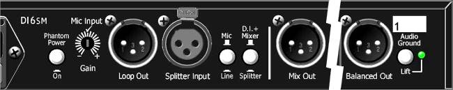
The channel outputs of the DI6SM enter the world via the Channel Out XLR sockets on the rear panel. (Channel 1 is shown for simplicity. The other 5 are identical.) The + In phase (HOT) output is on Pin 2, and the - Out of phase (COLD) output on Pin 3. The impedance of these outputs is deliberately on the high side to allow the DI6SM to operate into virtually any load without degrading the audio signal.

Pin I (Ground) is connected via the ground lift switch to the ground plane of the unit.
Channel Ground status is indicated by a green LED indicator. When the ground lift switch is pushed in, the electronic ground of the DI6
SM is connected by a drain capacitor to allow any RFI type signals to be drained to ground.
Apart from its basic Direct Box functions the DI6
SM offers two other modes of operation. See Below...


Mixer Mode


In this mode, the DI6
SM functions as a 6:1 line mixer with both balanced and unbalanced outputs. The DI6SM can operate in this mode at the same time as its original Direct Box mode.

Master section

The signals from all six input channels are combined into one signal with a Master Level control providing overall gain control.
This signal is then sent to the rear panel Mix Out Balanced XLR output, allowing the DI6
SM to easily connect to professional XLR based systems.  

Splitter Mode


Just by pressing in the DI/Mixer or Splitter switch on the rear panel, the DI6SM can change from a mixer to a splitter, and a Green or Yellow LED on the front panel (See above) will light up. In this mode it functions as a 1:6 splitter with a single Balanced input and up to 6 individual outputs with level/gain control and Ground lifts. A second switch to the left of this sets up the splitter as either Mic or Line. In Mic mode Phantom power is available for condenser microphones

Loop Output to rest of system if required (Red lead)

Input from Mic or Line signal (Green lead)

Use Switch to choose, after selecting Splitter on adjacent switch

Individual splitter outputs (Red lead)

Only one shown for clarity

The signal from the Balanced XLR input on the rear panel is controlled by the Master control which varies the level of the Input signal. This signal is then fed to each of the 6 individual balanced output XLR connectors where the individual output levels can be set with the front panel channel level controls. A Loop Out connector can send the Input signal to another DI6SM or elsewhere in the signal chain  


Please Note: In Splitter mode NO signal will be present on the Mix Out, and inputs via the Jack inputs SHOULD NOT be plugged in.

OK, now let's have a look at some examples of DI6SM operations

Personal Stage Mixer with Individual outputs to the rest of the World
This mode of operation can be used in conjunction with the individual channel outputs. For example, in a Keyboard setup the player could have up to 6 keyboards, samplers, or whatever patched into the DI6SM, send a discrete balanced signal of each to the stage box, which will split it to the FOH and Monitor consoles, and use the unbalanced Master output for their own personal onstage monitor.
On the other hand, if the Keyboard player has this big setup, but you're using a small rig without enough channels, you can set up a basic mix on the DI6
SM, and then run the Balanced output mix down to the stage box, which will split it to the FOH and monitor consoles, and use the unbalanced Master output for their own personal onstage monitor.
The same setup holds true for Drum Machines and other similar devices.
If Ground loops start humming, then these should be eliminated by lifting the individual Grounds via the switches next to each XLR output socket.


Adapting Domestic Equipment to the harsh world of Pro Audio
In Broadcast and Studio applications, and Disco/Club installations, the DI6SM can be used as an interface for Video Players (the audio part only!), Laser Disc Players, CD players, DVD players, Cassettes, to adapt them to the harsh unforgiving + 4dB balanced line real world that the rest of the system exists in.


Only One signal and everybody wants an Individual Output
Here's a very common situation. You're the AV Technician in a Convention centre (or anywhere else in the Audio world where things can happen without warning).
You've got a press conference that half the world's media want to record and the visiting VIP is microphone shy.
Even the one microphone is too many and the Video guys are already complaining about sight lines! What do you do? Stick half a dozen different mics up? No way.
You take an output from your house console, plug it into the Splitter input of the DI6
SM that you keep specially for occasions like this, and all your problems are over.
You've now got six individual balanced high level outputs, all with their own Gain controls to match individual level requirements, and with Ground lift to get rid of the hum that's always introduced by someone else's gear!
The applications for active variable level splitting are almost endless in the A/V, Broadcast and ENG world. With its ultra low distortion and
better than digital noise floor, the DI6SM will easily handle everything you're going to throw at it, day after day.


Here are some extra points to consider when using the DI6SM.

It's Phantom Happy
The DI6SM can be used to drive lines that have phantom power (20-48V DC used to power Condenser Microphones) present. This will not degrade the units performance.

It's got Headroom to spare On average the DI6SM will have 14dB more headroom than an active DI powered by one 9V DC battery, and 10dB more headroom than an active DI powered by two 9V DC batteries. As we all know, headroom in any system is a handy thing to have.

Very High Impedance Inputs The input impedance of the DI6SM is around 2 meg Ohms. (That's high) This means that the DI6SM effectively offers no load - it's not seen by the signal source feeding it.

How many times have you had the Bass player complain that as soon as you plugged him into your Passive (no batteries, therefore reliable) DI Box, the top end disappears out the window?
Now with the DI6
SM you can tell them they're going to lose more top end in their 20 foot guitar cable than by plugging into your AC mains powered (and therefore more reliable) DI6SM.


Speaker Level In is a No No!

The DI6SM is not designed to directly accept Amplifier output/speaker level signals. However, if you must capture that distinctive guitar amp sound without miking the speakers, or you've simply run out of microphones (don't laugh, it happens) then you can install the following circuit into a suitable ABS or diecast Box.In the diagram below it is the Black Box!

Black Box Circuit
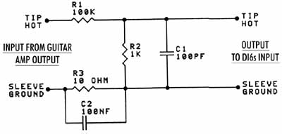
Note: Make sure the jack sockets you use are the insulating type.
This is effectively a 40dB pad/100:1 attenuator, so if you put 100 Watts in you'll get around 275 mVolts out. A much nicer signal levelwise.

Well, that's the how and why of your starter pack of DI6SM applications. Remember, if you come up with any special applications using your DI6SM, let us know and we'll include them in these notes next time we update them. Naturally we'll send you a little something for your trouble!


Back to Application Notes page

To DI6SM page


Thanks for visiting ARX. Contents © ARX Systems®